
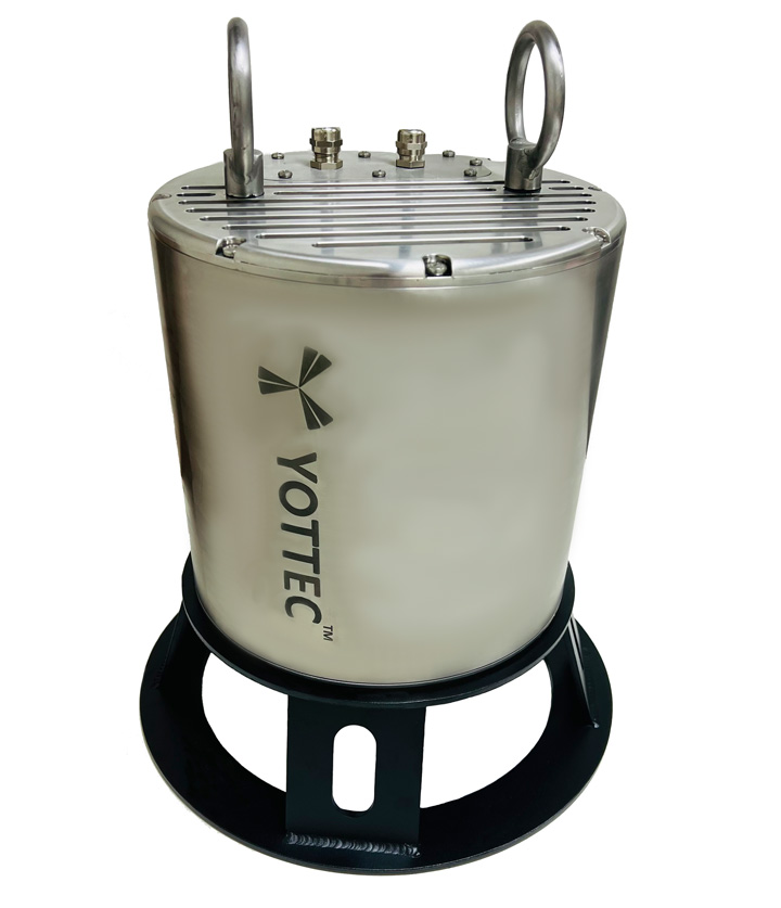
Global Navigation Satellite System(GNSS) Tracker & Telemetry
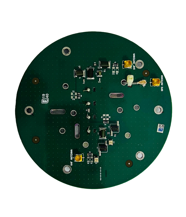
The GNNS tracker along with its telemetry unit consists of telemetry and ground receiver station. The transmitter (tracker) unit consists of GPS receiver to receive its co-ordinates from the satellite and a transmitter to transmit the Latitude, Longitude and Time of Day parameters after required modulation. The transmission is in L band frequency.
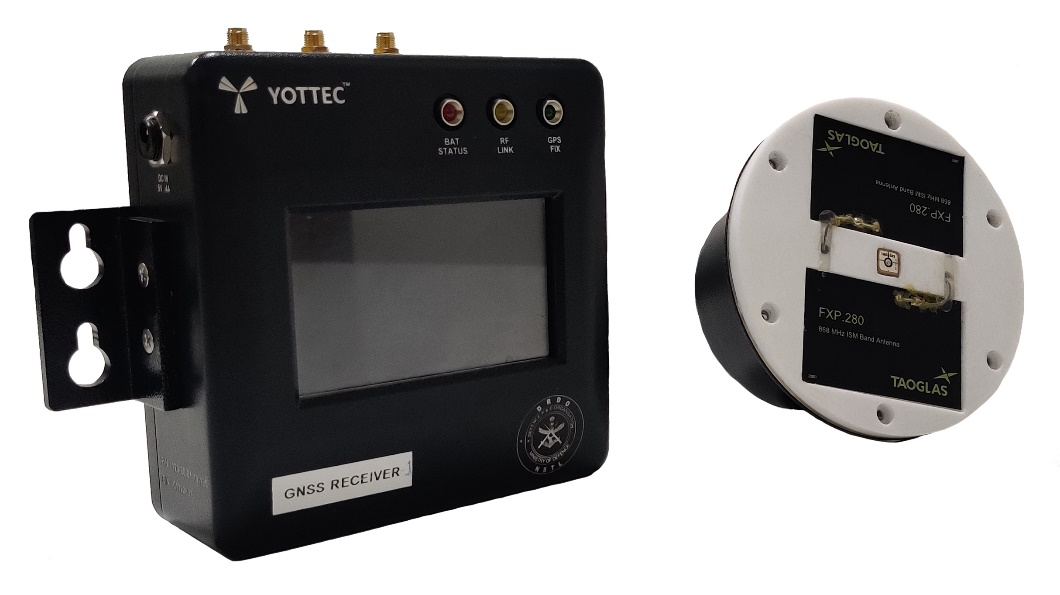
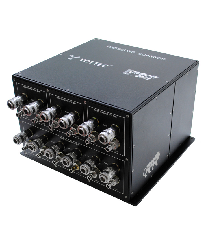
The ground station consists of RF receiver and GPS receivers along with the display unit. The Receiver co-ordinates data from the transmitter is computed with the ground receiver, GPS co-ordinates and the distance between the transmitter and the ground station is displayed along with the direction of arrival of the signal (Bearing angle). System operates on 28V DC supply from the torpedo GPS to the receiver system. The receiver unit should display all these parameters in real time
System is designed in house & qualified to meet standards JSS55555, MIL STD 810G & MIL STD 461F specifications.
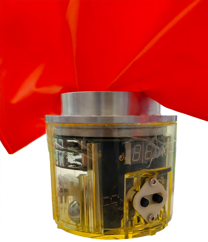
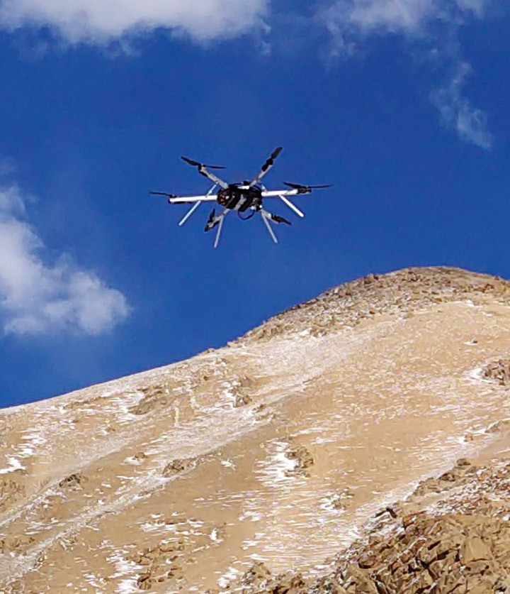
The Global navigation satellite system (GNSS) tracker & its telemetry is installed at the Nose of the torpedo unit and it is dropped from the helicopter. GNSS system will give the distance from the torpedo to the receiver at the ground station& the angle of the direction of signal arrival.
- GNSS Receiver Specification
| Number of Channels | 72 |
| GNSS Constellations | GPS L1 C/A , GLONASS L 10F , Galileo E1 B/C |
| Maximum Update Rate | 10Hz |
| Maximum Position Accuracy | Up to 2.5m CEP |
| Minimum Cold Start Acquisition Time | 26 Seconds |
| Minimum Reacquisition time after signal loss | 01 seconds |
| Tracking and Navigation Sensitivity | -161 dBm |
| Measurement Resolution | ± 0.003 |
| Cold Start Sensitivity | -147 dBm |
| Hot start Sensitivity | -156 dBm |
| Oscillator Type | Temperature Compensated Crystal Oscillator |
| Anti-Jamming | CW Detection and Removal. On board SAW Filter |
| Operating Temperature | -40 to 85° C |
| Protocol Support | NMEA |
| Interface Support | UART/SPI |
| Number of Antenna | 01 |
| Gain | -10dB ic @ Zenith |
| Gain @ 3.0V with LNA | 15 ± 4 dB ic @ 90 Degree |
| Impedance | 50 ohm |
| Polarization | RHCP |
| Axial Ratio | Max. 4.0 db @ Zenith |
| Input Voltage | 1.8V to 5.5V |
| LNA | Two Stage Active LNA with SAW filter |
| LNA Pout at 1dB Gain Compression Point | 8dBm to 11dBm |
| LNA Maximum current consumption | 23mA at Maximum Gain |
| LNA Maximum Noise Figure | 3.0 dB |
| Frequency | 1575.42MHz ± 1.023 Mhz |
| Patch Antenna Dimension | 10mm x 10mm x 4mm |
Controller Specification
| CPU Core | 32-bit ARM Cortex M3 |
| Memory | 64KB Flash , 20KB SRAM |
| Program Interface | Serial wire/ JTAG Interfaces |
GNSS Telemetry Module Specification
| Low Noise Amplifier gain | >15db , High IP3 |
| Minimum Data Rate over Air | 8kbits / second |
| Receive Sensitivity | -96dBm |
| Data Transfer Interfaces | UART – 3.3V Logic Level |
| UART Data Transfer Rate | 9600bps or above |
| Power | + 5V |