
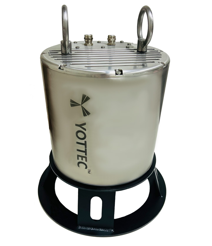

AMECS Test System is the Signal Simulator developed to test the AMECS system with simulated signals, as if they are generated from sensors.
This Test System (Signal Simulator) mainly consists of National Instruments PXI Express based chassis with Controller, Signal simulators for generating the required signals, DMM module to measure the output signals from AMECS system. Signal Simulator Programmer is the PXI Express Controller with RS-232 and USB Interfacing options to program the Data Read out, Control of Simulator.
- Function Generator mode
- Inspection mode
- Calibration mode
- Replay mode
- Specification
| CPU | Intel Core i5 4400E |
| Ethernet | Two 10/100/1000 Base T ports |
| DDR3L RAM 1600Mhz | 4GB |
| Hard drive | 200 GB or Higher |
| Operating system | Windows |
| GPIB Controller | Yes |
| Serial Ports (RS-232) | 1 |
| Compatibility | Fully compatible with PXI Express |
| Ambient temperature range | 5 to 50° C |
| Operating shock | 30 g peak , half sine , 11ms pulse |
| Random vibration operating | 5-500hz, 0.3g rms |
| Size | 3U sized , one system slot and eight peripheral slots |
| Board dimensions | Four wide 3U PXI Express module. |
| AC Input voltage range | 100 VAC to 240 VAC |
| AC Input frequency | 50/60 Hz |
| Operating Shock | 30g peak, half sine wave, 11mSec. |
The PXIe-1078 is 9-Slot PXI Express Chassis with PXIe-8840 Controller, 2 Nos of PXIe-4322 Analog Output modules, PXIe- 4081 DMM Module and Digital I/O module for the controlling of front panel toggle switches and the LEDs.
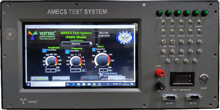
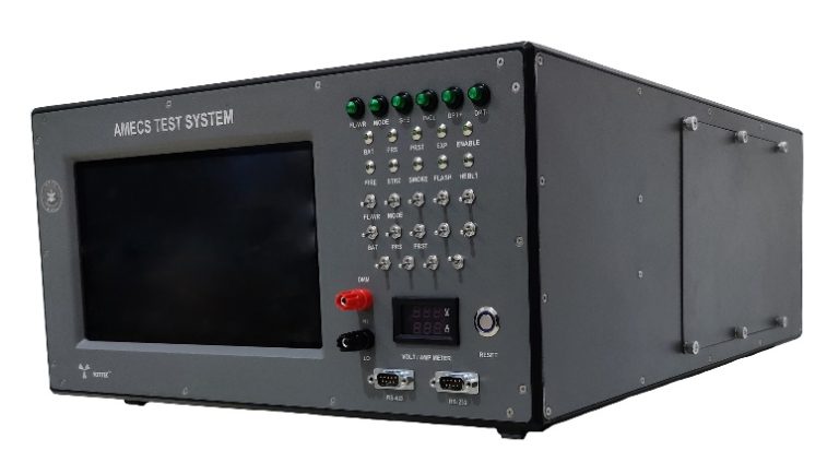
The Front Panel Interface consists of 10.1” Touchscreen display and USB port for the touchscreen functionality, 16 Nos of LEDs, 14 Nos of Toggle switches, 1 No of Pushbutton Reset switch, 28 VDC Power switch for AMECS, USB Ports, Serial Communication Ports (RS232, RS422), Ethernet Ports and DMM Connectors. RS422 signals converted to USB and connected to the Controller. 4 Nos of Hybrid Slots are spare for future purpose.
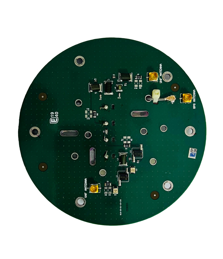
Voltage and Current monitor is installed on the Front Panel to monitor the Voltage and Current being drawn by the AMECS System. The Rear Panel Interface consists of 5 Nos of circular connectors for interfacing with AMECS System, 230VAC Input Connector, Power Switch and the Fuse, BNC Connectors for attenuated signals and an earth stud. Attenuator PCB is used to attenuate the generated signals from Analog Output module to be within the required ranges from AMECS System. AMECS System consists of the circular connectors to interface with Signal Simulator.
The standards used in AMECS Test System (Signal Simulator)
- Computer Serial Interface- RS-232/RS-422
- RJ-45 (Eight wire Ethernet networking cable)
- Universal Serial Bus (USB)
- International Electro Technical Commission (IEC), Standard Power Cord
- Operating Software used with AMECS Test System (Signal Simulator)
- Windows 10 Professional OS